

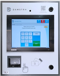
 DT – MK2
Specifications
 |
|
|
Device Type |
Power Requirements |
Data Connection |
|
DT-MK2 |
*GPO requires an electrician to install it. |
Ethernet / WIFI or 4G |
GPO Mounting Location
|
Figure 2. GPO mounting location |
The DIN Rail and Clipsal GPO are mounted inside the Damstra Terminal, to prevent users from being able to tamper with the equipment.
5 are recommended, however, if permitted, 4 can be installed and the use of a Test and Tagged Powerboard can be used. Recommended Components: Clipsal Part # 4PSO10 Description: 250V 10A 3 Pin socket outlet 2.5 modules wide Qty: 5 DIN Rail: As Required |
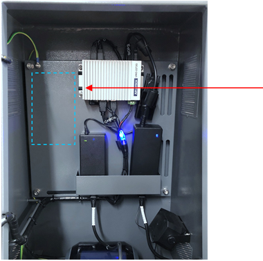
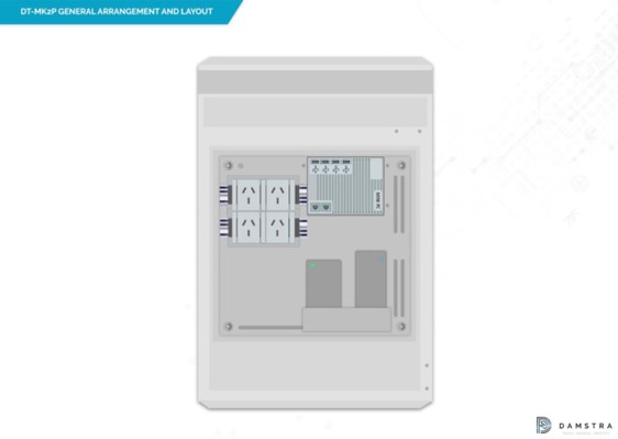
Figure 2a. Illustration of DIN Rail GPO positioning
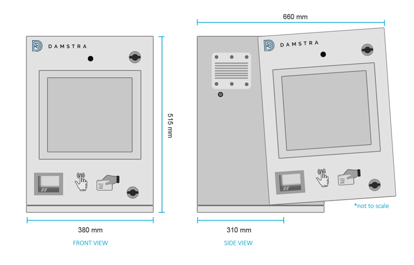
Dimensions and Installation Layout
| Note: If you are adding a WM4 Alcolizer, please refer to DT – MK2P GPO Mounting Location for further instructions. |
Electrical / Environmental and Connectivity
A suitable location should:
- be out of the weather (rain, wind and sun)
- provide enough wall mounting space for all units to be mounted
- provide sufficient 3G mobile service where required and
- be a suitable location for the workforce to find and access the system
Consideration should be given to the ambient air temperature. If ambient temperatures exceed 50 degrees Celsius alternate locations should be found.
|
Note: Failure to mount out of sunlight or in weather-affected areas will void all maintenance warranties and any cost of repair will be charged back to you. |
The unit can be mounted to most surface types; however, weight and usage need to be considered for hollow-type walls. Suitable mounting components should be used to ensure a safe and secure installation. Typically, this may include the use of UniStrut or similar mounting systems. On solid wall types (metal, brick, etc.), the units may be attached directly to the wall using suitable mounting methods.
Mounting Height
The terminal itself is recommended to be mounted with the top of the unit 160cm – 170 cm from the ground. This height has been found to provide a usable interface and comfort factor for persons, covering the widest range of a person’s height. This is flexible and can be adjusted at the site's discretion.
Mounting the Terminal
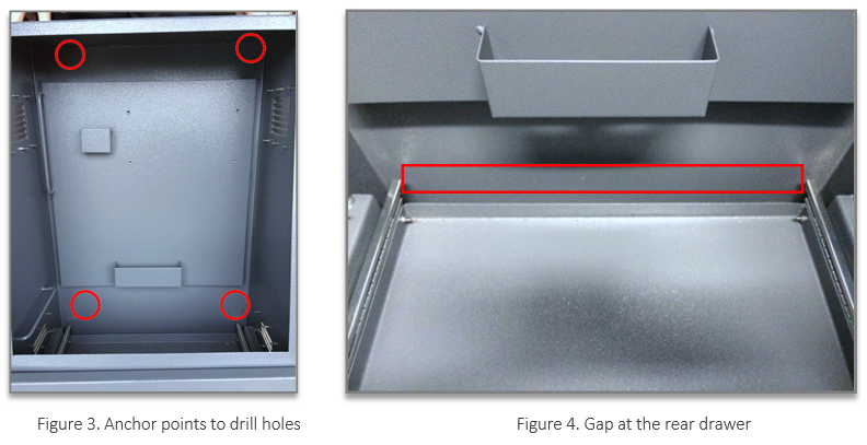
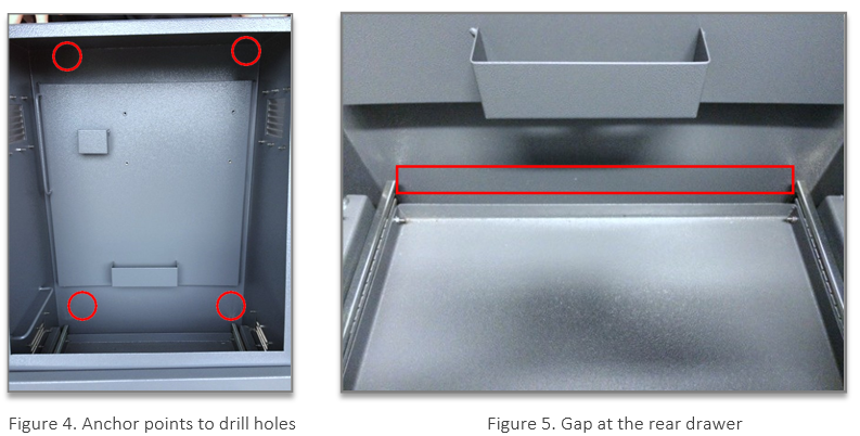
The terminal attaches to the wall via 4 anchors, located in each corner of the unit. The holes for these anchor points are ONLY to be drilled as per Figure 3.
Any holes required for conduit MUST only be drilled from the underside of the cabinet at the rear.
This typically includes power and data cabling, as well as any cabling associated with an alcoliser if utilised.
Care should be taken that cables and conduits entering from the bottom rear of the enclosure do not affect the printer drawer operation. There is a 35 mm gap at the rear of the drawer to allow for conduits and cabling as shown in Figure 4.
Do not drill any additional holes in any other areas of the enclosure. Failure to comply with this will result in additional charges upon return of the equipment.
Mount the unit to the wall or mounting equipment using appropriate screws/bolts. Tighten and ensure the unit is stable and secure
Clearance Required
Adequate clearance is required if there is any other device installed in the same location e.g. Alcolizer. The terminal door needs adequate clearance for it to be opened.
Reminders
- To open the cabinet, use the keys provided; ensure to lock it again after the installation is
- Make sure that all plugs inside the cabinet have the power to
- As soon as power is turned on, everything will boot up automatically and the terminal will be ready to use in a few minutes
DT – MK2P
Specifications
 |
|
|
Device Type |
Power Requirements |
Data Connection |
|
DT-MK2P |
|
Ethernet / WIFI or 4G |
GPO Mounting Location
|
Figure 2. GPO mounting location |
The DIN Rail and Clipsal GPO are mounted inside the Damstra Terminal, to prevent users from being able to tamper with the equipment.
5 are recommended, however, if permitted, 4 can be installed and the use of a Test and Tagged Powerboard can be used. Recommended Components: Clipsal Part # 4PSO10 Description: 250V 10A 3 Pin socket outlet 2.5 modules wide Qty: 5 DIN Rail: As Required |

Figure 2a. Illustration of DIN Rail GPO positioning
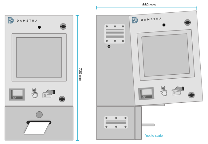
Figure 3. Dimensions and Installation Layout
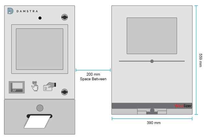
Figure 3a. Alcolizer positioning and distance between the terminal
Electrical & Alcolizer Communication Cable Location
As each installation is different, we recommend that electrical cabling is entered through the left-hand side (Red Circle) and the Alcolizer serial cable from the right-hand side (Green Circle) on the base of the cabinet.
We recommend that after you drill the holes out, appropriate cable glands be inside to ensure vermin cannot enter the terminal.
In our experience, electricians often cut and splice the COM cable (which should be avoided at all costs), If splicing occurs this would must be carried out professionally and all joins must be soldered and tested.
The Alcolizer should be installed as per Diagram 3a with the displays aligning, but both units at an appropriate height so that personnel can use the system safely.
|
Note:
|

Figure 3b. Electrical & Alcolizer Cable Holes
Electrical / Environmental and Connectivity
A suitable location should:
- be out of the weather (rain, wind and sun)
- provide enough wall mounting space for all units to be mounted
- provide sufficient 3G mobile service where required and
- be a suitable location for the workforce to find and access the system
Consideration should be given to the ambient air temperature. If ambient temperatures exceed 50 degrees Celsius alternate locations should be found.
|
Note: Failure to mount out of sunlight or in weather-affected areas will void all maintenance warranties and any cost of repair will be charged back to you. |
The unit can be mounted to most surface types; however, weight and usage need to be considered for hollow-type walls. Suitable mounting components should be used to ensure a safe and secure installation. Typically, this may include the use of UniStrut or similar mounting systems. On solid wall types (metal, brick, etc.), the units may be attached directly to the wall using suitable mounting methods.
Mounting Height
The terminal itself is recommended to be mounted with the top of the unit 160cm – 170 cm from the ground. This height has been found to provide a usable interface and comfort factor for persons, covering the widest range of a person's height. This is flexible and can be adjusted at the site's discretion.
Mounting the Terminal
The terminal attaches to the wall via 4 anchors, located in each corner of the unit. The holes for these anchor points are ONLY to be drilled as per Figure 3.
Any holes required for conduit MUST only be drilled from the underside of the cabinet at the rear.
This typically includes power and data cabling, as well as any cabling associated with an alcoliser if utilised.
Care should be taken that cables and conduits entering from the bottom rear of the enclosure do not affect the printer drawer operation. There is a 35 mm gap at the rear of the drawer to allow for conduits and cabling as shown in Figure 4.
Do not drill any additional holes in any other areas of the enclosure. Failure to comply with this will result in additional charges upon return of the equipment.
Mount the unit to the wall or mounting equipment using appropriate screws/bolts. Tighten and ensure the unit is stable and secure
Clearance Required
Adequate clearance is required if there is any other device installed in the same location e.g. Alcolizer. The terminal door needs adequate clearance for it to be opened.
Reminders
- To open the cabinet, use the keys provided; ensure to lock it again after the installation is
- Make sure that all plugs inside the cabinet have the power to
- As soon as power is turned on, everything will boot up automatically and the terminal will be ready to use in a few minutes

Comments
0 comments
Please sign in to leave a comment.